During the past week I have made some general repairs to the printer since the updated parts. At the time of upgrade I did not take the time to properly finish the wiring. I had jumper wires with alligator clips for the thermistor, hot end, and the cooling fan for the hot end. One day while printing I hit the wires just right and caused a short. This caused some vinyl wire coating to melt and some of the wires to fuse together!!! Scary moment when it happened. I will say that I never leave the printer unattended so at least I was right here. I have now corrected this wiring, soldered, and tucked the wires up neatly. No damage was caused, except to a few of the jumpers I had been using.
Additionally the kapton tape on my heat bed has been in rough shape. This was fine since I just strategically printed in select areas. I had a large item to print and decided it was time to replace all the kapton tape again. It looks much better now.
Showing posts with label Upgrades/Improvements. Show all posts
Showing posts with label Upgrades/Improvements. Show all posts
Monday, April 6, 2015

Sunday, December 21, 2014
Problems fixed!!!!
I cannot even begin to say how excited I am to bring these updates. I finally got my printer back up and running! It has been down since spring when I had the melt down on the extruder. The second extruder just did a crappy job. I couldn't find any solutions to the multitude of problems I was experiencing. It was really upsetting and made me not even want to try. I spent multiple Saturdays for hours on end trying to make it work. Finally I admitted complete defeat. I was on the verge of cannibalizing my machine to make a new one all together.
I decided I was going to purchase a new hot end as a last effort, if it didn't work I would then indeed cannibalize my machine. Instead of choosing some random supplier and risking getting some garbage extruder like I did with my first replacement, I decided to go to my original supplier makerfarm.
I purchased a new Hexagon hot end, a new hobbed bolt, and a new Greg's Accessible Extruder (printed parts only since I figured my previous bearings and everything were still good). I also purchased the extruder so that I knew that the gears would mesh right since mine were very worn. I put my full trust MakerFarm

The day it came I spent the rest of the night getting everything together and in place.


I decided I was going to purchase a new hot end as a last effort, if it didn't work I would then indeed cannibalize my machine. Instead of choosing some random supplier and risking getting some garbage extruder like I did with my first replacement, I decided to go to my original supplier makerfarm.
I purchased a new Hexagon hot end, a new hobbed bolt, and a new Greg's Accessible Extruder (printed parts only since I figured my previous bearings and everything were still good). I also purchased the extruder so that I knew that the gears would mesh right since mine were very worn. I put my full trust MakerFarm
Hot end and fan. It was stressed to me how important it was to cool the body of the hotend during the print. Do not skip using a fan that blows on the body! Not on the tip where the plastic comes out, just the body. (Now makes me wonder if that was part of the problem with my second hotend?) The other thing I love about this new hotend is that little rubber booty that holds in the thermister and insulates the tip of the extruder. Very nice upgrade!
Extruder . Looking good :)
I then went into calibration mode (haha seems there is never ending tweaking with these machines) I followed the steps here for calibration. Everything worked like a charm. Now time to test the machine out. All of this update actually happened in mid November but I had to hold off for specific reason :) More revealed in the next post.
Thursday, April 17, 2014
Hot end replaced
So I got the printer back up and running. I replaced the hot end, thermister, and resistor. I ran into a compatibility issue though! I ordered a new J-hotend not realizing there could be some major difference. When I took my old extruder off I instantly noticed a difference. My old one is on top. The new one on the bottom....


Notice anything difference besides for color and the resistor stuck in it? How about that nice brass fitting on top of the new one.... It is being used to hold a liner in. In the old extruder there was an open set screw to hold the liner in. Of course this new extruder wont fit my print head...
In this picture you can see the bottom of my print head. The old extruder used to nest nicely in that depression. The new one the fitting is in the way like stated.
My fix? Drill it out. I just used a big drill bit and kept drilling deeper and deeper until the clearance was correct. I was then able to mount the new extruder.
When it came time to print I noticed I had to set it at 20° hotter to get good flow? Is this an issue with the new head? Or maybe the thermister is just out of whack compared to the old one? Only time will tell.
Thursday, January 30, 2014
Fan Cooling
So after my recent issues I decided it was finally time to get my fan hooked up to the electronics board. I had designed my enclosure with a slot on top to fit a fan for forced cooling across the heat sinks. Up until now I have had a little dinky fan blowing through the holes in the end. Not really effective for anything probably.
I have a pile of old power supply fans. This one came out of a server power supply and is very powerful. I hook it to a 9V battery now and then for some rapid cooling on the spot. I figured it would be a good match for this.
 I designed this little adapter for it. Basically it takes the fan opening and channels it down to be a slot that matches up with the board enclosure. I printed the holes at the exact diameter of the screws knowing it would be slightly smaller as most inside diameters are when 3d printing. This smaller diameter allows me to treat the machine screws as self tapping (threading the holes as turned into them).
 Next I drew up this little fan shroud to make sure I dont stick my fingers in ;)

I have a pile of old power supply fans. This one came out of a server power supply and is very powerful. I hook it to a 9V battery now and then for some rapid cooling on the spot. I figured it would be a good match for this.
Stack them all up and it is complete. I "glued" the adapter directly to the enclosure using pure acetone and a q-tip. I went around the edge a few times to seal up any little gaps I saw.
Well once I hooked this to my power supply I got quite the surprise. Sure I knew it was a few more volts but dddddaaa####*** this thing is so turbo you can feel the air blowing out any orifice from a few feet away. Needless to say, I am going to install an inline switch and turn it on only now and then during longer prints. I might need to downgrade the fan a little since it is just so powerful.
Tuesday, June 11, 2013
Safer Wiring!
Way back in the beginning when I wired up the heat bed I used some old computer cables that I had. Seen Here It worked for a while and was great except for one thing.. The wire is 16ga and couldn't handle the amps that were required for the heat bed. I noticed this within a few weeks of printing when the plug started to turn brown. The picture below shows the plug as it was when I just re-set the printer back up.


The yellow wire that was in the power supply is severely damaged. It also melted the protector plate on the power supply. I knew it was too hot and never printed without me sitting right there. I also always kept a fire extinguisher next to the printer in case the worst happened. I had tried to extend the life of the plugs by attaching some ceramic to pull the heat out and then have a mini computer fan blowing on that.
Upon moving into the new house I felt very obligated to correct this problem. Especially because I eventually plan on this being set up in my workshop in the basement.
I recently did some rewiring of the bathroom lights (no worries it is all up to code and has the proper gage wire) and I had a small scrap of 14ga wire that I had cut out. I also had an extra single pole switch(since I now have 3 way lighting in the bathroom). I cut off the plugs and wired it properly.

There is a celebrity appearance in this photo of our really tiny kitten Wronskian (Wronny).

I will print a box that is a little smaller and a cover plate as one of the near future projects.
I did still leave the computer cable with molex connections hooked up for the cooling fans. It made it really easy to just plug the fans in and I can unplug them when I want. Further down the road I will have them on toggle switches.
Friday, March 8, 2013
Warping and sticking in Geneva
So I will start by saying after I did the recent tape job (which looks great) I have been having some major issues with warping/curling. I dont know if this is because of the weather or the fact that the apt is a little cold but it has been very annoying.
For those of you who dont know what warping is read this: When printing the plastic it will cool down and shrink. On larger prints the lower layers are cool by time the next layers print. As the above layer cools it pulls the part towards the center as it shrinks. This will cause the corners of the print to pop of the bed and sometimes even cause the entire print to fall off.


For those of you who dont know what warping is read this: When printing the plastic it will cool down and shrink. On larger prints the lower layers are cool by time the next layers print. As the above layer cools it pulls the part towards the center as it shrinks. This will cause the corners of the print to pop of the bed and sometimes even cause the entire print to fall off.
I wanted to try a few things to see if I could stop the curling. The far left print you can see how much the corners came up by time it was done. This was just plane printing on my clean surface. Way more curling than ever before while printing on my ceramic.

The Middle was a trial using water and glue mixture. The water evaporated off the bed and left a thin film of glue. This did help a lot as you see but still not perfect. Next I tried some acetone based (small % though) nail polish remover. This did help still but I wasn't 100% happy with the results.

I went to amazon.com and purchased a small 4 oz bottle of 100% acetone to dissolve some ABS in. After waiting a week for it to come in I took a sauce jar and put in 2 ounces of the acetone and a few scrap parts. When I woke up in the morning the parts were completely gone! This is ABS juice that is becoming a more common practice. I know a smaller jar would help contain the fumes but this is all I had for now.

Now that I had the abs juice I applied some to the print bed with a q-tip and printed the next part I needed. Boy did I have fun trying to get this off! I tried letting it cool and still couldnt get it off. Next I tried the freezer to see if it would shrink and pop off. Nothing. Next I took a hammer and screw driver and had to dig under it in a few places to pop it off. HOLY CRAP was it stuck. I damaged the tape underneath getting it off. That made me think of something....

For my next piece I decided I would need some leverage to pop it off. I placed two small strips of kapton tape 75 percent of the way underneath at either end. I then covered them with ABS juice and clicked print. It printed perfectly over the tape and 0 warping again! When it was time to remove the print I just lifted up the tape and with a little force, BINGO it popped off. I can't wait to try this method again. I dont see why it wouldnt work. It reminded me of taking the batteries out of something when you have to pull the little string to pop them out.

Right after popping the print off using the tape as pull strings

At the end I had something fun to play with! Thing1642 a Geneva wheel. Really a cool little indexing device.
On a side not we will be moving soonish so I dont know how this will affect my printing, I foresee some new calibration needed after moving.
Monday, February 18, 2013
New tape, and starting print code

My print area is framed by the blue corner marks. The pencil rectangle is on the ceramic and couldn't get it off. It is not as wide as I would like because at the max height my cooling with crash into the frame.
The next big thing I did I cant really show a picture of. It is a programming thing. In KISSlicer and other slicing programs it is common practice to put some start code and end code to add to every print. Such as home all axis, reset extruder, etc. Here is what I did and why;
G-code Prefix
G28 ; home all axes
G1 X0 Y0 Z10 ; move to z10
G92 E0 ; reset extruder
G-Code Postfix
M104 S0 ; turn off temperature
G28 X0 ; home X axis
G28 Y0 ; home y axis
M84 ; disable motors
The Key line is the underlined one. What this does is bring the z level up to 10 before it starts to print. It will then move on a very nice linear diagonal until it hits the point where the print is going to start (in my case usually (100,100,0). The reason I did this was because it allows it to clear the tape in-case there is a wrinkle or bubble and not rip the tape up. Also if a little piece of plastic is hanging off the nozzle it might catch the tape edges too. If you look in my previous posts you will see where the tip dragged and ripped the bed the shreds. Now if it is going to drag it will only do it at the start point of print instead of the path to get there. This happened more than a few times in the past because I like the first layer so thin for ultimate adhesion.
Monday, December 31, 2012
Bringing in the new year with a kiss
So I made an upgrade yesterday to Kisslicer to see how it would do. First thing off it was extruding any material. I finally found the setting to make it work. Shorty after I crashed the head into the table. Well this required a whole bunch of calibration to fix. I kept printing my little calibration cubes like normal until I was "satisfied". Nothing better than a kiss on New Years right?
Well next I decided to print something New Years themed. Thing 36257 was just what I needed. I decided to print 3 and make little tweaks between each of them. They all came out pretty good but still had some work to do. Enjoy your New Years and be safe!

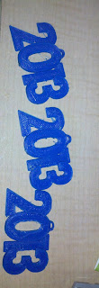
Well next I decided to print something New Years themed. Thing 36257 was just what I needed. I decided to print 3 and make little tweaks between each of them. They all came out pretty good but still had some work to do. Enjoy your New Years and be safe!
This is a timelapse of the 2013 item being printed

One of them

Picture of all 3
Sunday, October 7, 2012
Print Bed Leveling Screw Position
So I was having a little issue yesterday when completing the leveling and forgot to include it in the last post. I made one more minor change. I flipped 3 of the 4 bed screws so that they look like this.

Wood, nylon spacer, washer, M3 nut bed, then M3 nut
It had to do with the same issue of restriction. I was finding by tightening the bed to the wood could still cause some warpage. If I pull down one corner to much it will flex across the opposite diagonal. To combat this I only tightened 1 corner with the bolt down (opposite of picture above). The nuts holding the bed on the other three corners were left off. This allowed it to "float" up and down on the bolts while I made adjustments to the leveling springs. I also clamped the bed to my ceramic plate since that is a known flat surface. I was able to adjust the bed to be level and make sure that I wasn't going to pull down on a corner when locking it in place (flex issue on the diagonal as stated). Once I was happy with the leveling I just finger tightened some nuts on the 3 loose corners to hold it in place. This system as allowed me to get way more level then I ever was before.
Saturday, October 6, 2012
Print Bed Leveling.. Iteration 4
Well after trying a few different things and not getting them to work right, I had to buy a few supplies from McMaster Carr to get this final iteration. I had some 6/32 T-nuts already for the wood but couldn't find 6/32 cap screws anywhere. I had brass machine screws but realized that was going to be a pain to try to get a flat head screwdriver in and position to level the bed. I wanted cap screws so I could use an allen wrench to tighten them like before. I went with 1 1/2" to make sure I could make it through the base acrylic, springs, and into the t-nuts.


View showing acrylic and springs (3 of 4 showing)

Now look at this stack up compared to iteration 1! much more respectable. I haven't even tightened the springs down yet. So now it is acrylic, springs, wood, nylon spacer (to allow for room for the wires and the screws sticking through), heat bed, and my high precision ceramic surface.
Now if you are asking yourself why did I decide to do it this way? Well remember my 2nd layer of acrylic was extremely warped so I couldn't get the bed level. The four corners were to restricted to each other that it was difficult to adjust. Now the left and the right have independent suspensions. With the less restrictions I should be able to control the leveling easier.
Another major benefit of doing it this way was the tightening it self. Originally (before iteration 1 of new leveling), the spot for a allen wrench was up near the bed it self. I couldn't get the wrench in there, I would have to hold the head with a pair of pliers and turn the nut beneath with a small crescent wrench or another pair of pliers. It was very difficult to make adjustments. To fix this, when I first started re-leveling I just flipped the screws so I could fit my allen wrench underneath and hold the nut with a pair of pliers. It wasn't perfect and still a pain to level. And this is when I noticed how bad the acrylic was. Anyways after all of that and I saw this design idea, I decided to adapt it. No more holding the nut! It is pressed into the wood so all I need to do is adjust the screw with an allen wrench. The ease of leveling is amazing.
Wednesday, September 26, 2012
Print Bed Leveling Idea 1.. New iteration please!
So I wanted to re-level my print bed. Easier said then done. When I went to do it I realized the acrylic was extremely warped and causing a major issue trying to get it level again. The leveling was way worse then it was if I would have left it alone. So I took to the forums. I liked something I saw, so I decided to take a similar approach and see what happens.


Step 1: Use something else to space the 2 layers of acrylic instead of the typical spring system. I used these nice little scavenged ceramic parts from work. There is just enough clearance for the belt clips.

Step 2: Use 2 strips of 3/8" x 1.5" wood and drill holes for this style "nut" to secure in.

Step 3: After all 4 are in place, use a bolt to compress the spring and spring load the wood the platform

Step 3 alternate view: With a careful eye you should be able to see the warpage on both sides showing. It's really bad in the middle.

Step 4: Put the larger acrylic over the smaller as before, but now the springs are on top supporting the wood, not under it separating the two acrylics. Using the heated bed spacers, suspend the headed bed above the wood. And if you have a precision ground high grade ceramic plate like I do, put on top of that.
Whoa Whoa WHOA!!! Look at how tall that is and all the wasted space! Design change time :) It will be in the next post. More details on why I want to level the bed like this in that post. Remember, this is not the option I choose! See the next post.
Saturday, September 22, 2012
New extruder... not exactly what I wanted
So here I go.. I start putting the extruder together and it says to use some 1.75mm filament to align the gear. I realize that all I have is 3mm filament. My mistake for not reading everything! I will deal with it later, maybe another printer at some point or just changing mine a little. For the 49 bucks I may as well keep it.
Wednesday, September 19, 2012
New Extruder!
So I know it has been for ever since I have updated. Good news, now that it is getting colder out, and now that I have a new purchase, I should be up and running again soon. Things on my list to do
1. Buy new color spools :complete
2. Update Slic3r
3. New extrude head intalled :almost there!
4. Additional power supply to power the fans and control board since heat bed is pulling a lot right now
A while back I funded this kickstarter by QU-BD. I did a $49 pledge to get a single extruder just to try it out. It arrived yesterday. It is amazing how many backers they have had! Good for them, I am really excited and hope things work out well. This weekend I will hopefully bash out some of the upgrades and get printing! It will be in a new color too now that I have another nozzle. If things go well I might modify my machine to make it the dual extrusion further down the road.
Here is a pic of what was included, should be everything I need to get it up and running.

1. Buy new color spools :complete
2. Update Slic3r
3. New extrude head intalled :almost there!
4. Additional power supply to power the fans and control board since heat bed is pulling a lot right now
A while back I funded this kickstarter by QU-BD. I did a $49 pledge to get a single extruder just to try it out. It arrived yesterday. It is amazing how many backers they have had! Good for them, I am really excited and hope things work out well. This weekend I will hopefully bash out some of the upgrades and get printing! It will be in a new color too now that I have another nozzle. If things go well I might modify my machine to make it the dual extrusion further down the road.
Here is a pic of what was included, should be everything I need to get it up and running.

Sunday, May 20, 2012
Calibrating again

So I decided recently that although I was happy with my prints, it was time to yet again try to improve them. I picked this object because I was previously having problems with overhangs, the nozzle being to hot, and extruding too much filament.
After printing a bunch of simple test perimeters (1 extrusion width cube walls 20 layers thick) at all different layer thicknesses, I decided to drop my layer height from .32mm to .28mm. I also adjusted my hot end temperature. I was running 250 degrees C but now lowered it to 220 degrees C. In slicing objects I set my retraction to .9mm. Finally, because of the lowered layer thickness there was just too much filament being extruded. I set the extrusion multiplier to .8 and now its just right.
This is how a hollow cube printed with those settings. Wayyyy better than anything before with skinny features and bridging. With my previous settings the legs would have just melted and the print would have never completed. I used to have huge strings between features too. Now the strings are minimal and easy to clean up. There are also no massive drag marks in the solid surface from the nozzle.
Thursday, May 10, 2012
Gen6 Board Enclosure

Ok so nothing really that new here for many RepRappers, but I made my own gen6 board enclosure. It was a really long print and took a lot of material (relatively to my other prints). I can now enclose my electronics to help protect them. A vent on top was placed for future hook up of a fan.
In my older posts you will see that the board is mounted on the acrylic on the face of the machine. This limited my z-height to 43mm. I mounted the acrylic on top of the unit and spent hours rerunning the wires and getting them to look neat and out of the way. Now I have a max Z of 82mm (could go a little higher but being safe)

Monday, April 23, 2012
Software Upgrade
So I decided to make the firmware switch from Sprinter to Marlin. Wow what a difference! Before on sprinter my circles were out of round by 1.1mm and were very jittery. With Marlin my circles are out of round by .3mm and runs smooth as butter. It also runs so much quieter.

This is a Wades Extrusion gear comparison. The one on the right was Sprinter, the one on the left Marlin. Although it may be hard to tell from the picture, the Marlin print is much more round. The rest of the print quality on this part had major improvements.
Some thoughts on Marlin.... The change over was very difficult for me. It took a few nights and hours of programming to get it to work correctly. It definitely improved quite a lot but was very frustrating. The direction are very unclear at best, and because every printer runs differently it was hard to get it configured.
I also decided to get Autodesk 123d this past weekend! Pretty cool, I like it better than sketchup but still nowhere near Solidworks (which I wish I had)
Tweaking
So I spent a long time playing with different temperatures and layer thicknesses. I also seemed to be having too much fill causing the nozzle to drag on solid filled areas. I adjusted the ratio of filament output.


All of my test pieces, was keeping prints small to not waste filament and just test with settings. My optimal settings were 240 Degrees C, .95% extrude ratio (extrudes .95% of calibrated rate), Layer thickness .32mm. Ambient room temp for all prints so far has been around 70-75 degrees F
These tests are using Pronterface (GUI), Sprinter (Firmware), Slic3r (Gcode generator) and Google Sketchup.
New Print Bed
So previously I had mentioned that I upgraded to printing on a piece of glass from the Home Depot. Well, that was working very well but I was still getting some warping issues and sometimes the glass wouldn't seem that hot. It was suggested to make ABS juice out of dissolved ABS scraps, but I didn't really want to store acetone in my apartment.

 The ceramic heats more evenly than the glass ever did, and I do not have insulation under the heatbed like many suggest. The ceramic holds the heat very constant. The ABS would not stick to the bare ceramic so I still needed to use Kapton Tape. I purchased a 1" wide roll from Amazon. So far I have had no warping and the adhesion has been awesome. Even on some bigger prints (no pictures of those)

An opportunity arose to get a hold of a sheet of flat ceramic. This is a little bigger than the heat bed, but the corners are rounded enough to make it fit. It is flat and parallel within .0002" but failed due to a large chip on one of the edges. Instead of letting it get shattered in the dumpster I asked permission to test this $1095 plate as a print surface.

Wednesday, April 11, 2012
Extrude Axis Cooling Upgrade
This is a sweet upgrade I did. Haven't tested the cooling capability, but it looks like it will work well

Here is a cooling kit that I purchased for just 9.99! 2 heat-sinks, thermal paste, double sided thermal tape, and a heat-sink with build in fan. It also has to quick attach pushpins.

I immediately whipped up a bracket to fit around the extrude motor and line up with the mounting holes. The holes needed slight reaming. The print as a hole looks beautiful and only required about 300mm of filament

End view of fan heat-sink to see how bracket was fitted. Underneath the copper I put down a full layer of kapton tape, this was to protect the motor from the thermal paste but still provide good conductivity. It also works as a vibration shield.

Here is a side view showing the quick push pin. Hopefully I will be doing some heat testing tomorrow!
The smaller additional heat-sink might be placed on the face thats showing in the picture if needed. If not both extras will be put to use on the other motors.

Update! 4/23
The extrude motor was still getting fairly hot so I added the small heat sink to the side with some of the double sided tape. Major improvement.
Monday, April 9, 2012
Temporary Cooling
Some of my current temporary cooling for my stepper motors. On the two 30-40 minute prints I have done the Extrude Motor gets very hot. Not to mention the X and Y motors get pretty warm. I can only imagine what they would be like for a few hour print.

A thin ceramic plate attached to the extrude motor with a cooling fan blowing down on it did the trick! Only limits me to a small print area for now (ok no big parts yet)

Haha the fan wiring I'm proud of. I used an old scavenged server power supply fan with a very high airflow rate. I ran the wire back to a nine volt battery that is taped in place to one of the Z axis motors. I also hooked up a scavenged 115/230V switch out of a power supply (works just like an on off switch if you know how they work). Some alligator clips, electrical tape, and a paperclip make it complete. Oh yeah and the zip ties holding the fan so it blows onto that ceramic plate

X axis cooling. Now I particularly like this one. The are three ceramic L shaped pieces with a hole in them. The fit pretty snug to the motor and were easily zip tied in place. Will do the same to the Y axis.
Ceramic is an excellent conductor of heat. These small amounts of ceramic are very efficient at pulling heat off the motors. These ceramic parts are scrap parts from my workplace and I do have permission to use them.
Subscribe to:
Posts (Atom)