Monday, December 31, 2012

Bringing in the new year with a kiss

So I made an upgrade yesterday to Kisslicer to see how it would do. First thing off it was extruding any material. I finally found the setting to make it work. Shorty after I crashed the head into the table. Well this required a whole bunch of calibration to fix.  I kept printing my little calibration cubes like normal until I was "satisfied". Nothing better than a kiss on New Years right?

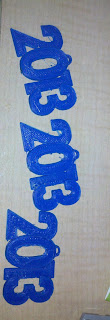
Well next I decided to print something New Years themed. Thing 36257 was just what I needed. I decided to print 3 and make little tweaks between each of them. They all came out pretty good but still had some work to do. Enjoy your New Years and be safe!


This is a timelapse of the 2013 item being printed
One of them

Picture of all 3


Friday, November 30, 2012

Mountain Top Pt 3

I wasn't completely satisfied with the mountain landscape. Yeah I know it still needs ground foam and trees and details, but it was missing something. The wife had to make a trip to AC Moore for some supplies, so I tagged along. I found a much bigger selection in the scene-a-rama section. 

I picked up some thin sheets of plywood (1/32 and 1/164), to build structures out of later. I also picked up some little containers for when I mix my paints. I wanted something with a lid so I could shake it. Also got a carton of casting plaster, since I know I will need the rockmolds again elsewhere on the layout. They had a Ripplin' Water Kit I figured I would try out at some point. And finally another rock mold.

 This came with smaller rocks, 10 on the same size tray instead of 3. It was just a basic kit including only the molds and plaster. 

Those are some nice rocks you got there

Test fit

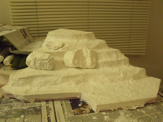
Spackled and glued in place 

Remember this is what it looked like

Landscape of mountain top: Complete! Now I just need to start adding ground foam, tullus, trees, etc. Look for my next update, hopefully soon!


Tuesday, November 20, 2012

Mountain Top Pt2

So now that the mountain was covered, it was time to make some rocks! The rock mold only made 3 rocks, each were pretty big (since I'm in Z-scale) but more to come on rocks in Pt3 ;)

Test fit of the 3 rocks from the mold

I glued the rocks on, then sealed the gaps using a lightweight wall spackling. I love using this stuff on my layouts. If you use it and find it hard to spread out, just use a mister bottle and wet it down. It will take longer to dry but when it does it will be much smoother. 

A close up of a rock

So now it came time to color the rocks. The kit came with it's own paint but I decided not to use it. It was in limited quantity and I didn't want to run out and not be able to match it later. So I used some acrylic paints I had on hand.

I mixed up a light brown, a dark brown, and a very watered down black. You notice I mixed in bottle caps, this was because it was all I had available, and it allowed me to control how many droplets to water ratio. 

The rocks get speckled in the different shades of brown (1/3 area light 1/3 area dark), then the whole surface covered in watered down black.  

remember this is what it looked like before paint

Next I had to cover the flat areas with a concentrated dark brown mixture. This is to resemble dirt. This will later be covered in ground foam, but any area that is thin or shins through will show the dark brown. Looks pretty good eh? (white spot on-top of the right rock is the sun BTW, it is actually the same color as the face)

Part 3 will take the mountain to the next level of detailing. 


Sunday, November 18, 2012

Mountain Top Pt1

While the wife and I were shopping in the craft store so she could pick up some scrap booking things. This caught my eye.

 I have never purchased a scenery kit before (except buildings) on my other layouts. I knew I had a mountain top to decorate, so I figured I would see how this kit recommended to do it. I knew woodland scenics does tons of model railroading supplies, so why not trust there diorama sets? I knew that the trees are not going to be to scale for my use, but at least I got some rock molds and some good directions.

Around 2 weeks ago I decided to open the kit and see what becomes of it. The Kit contents: Plaster cloth, glue, spray bottle, rock paints, earth undercoat paint, shaker, different turf media colors and grades, tullus, casting plaster, rock mold, and an instruction booklet.

I modified the foam slightly to have a nice steep face since the rock molds are pretty big. (The big rock about 36 scale feet tall by 70 scale ft wide)

 After wadding up some strips of news paper to help decrease the intensity of some of the steps, I got to work with the plaster cloth. 

I made sure to cover up the back side too. This was to help complete a shell so that it wont be able to peel up on the edges and come disconnected. 

Nice complete coverage!

Saturday, November 17, 2012

Let the Land Take Shape

Next I used my pink insulation to start replacing the paper cards that I had folded up before.

Start with some basic shapes

Next fill in some thick sheets and mark out where to remove material

Using a rasp I cleared away the material

When I decided to put in that upper loop in the corner, I knew it would be in a mountain

Sooooo... Heres the basic shape of the mountain. The tunnel port you see is scratch built, and will be one of my next posts! Stay tuned.

Elevation Trials

After deciding on a track layout, you need to decide what elevation changes are needed. So this past winter I did out some simple sketches and shading to show the different levels. 


Here are the sketches I did.

Time to start laying track!

Track laid down

Added a raised loop I never planned on

I used paper folded up to do a mock up of the elevation changes

Now time for the land to take shape :)

Wednesday, November 14, 2012

Prelim Layout

Back in my second year of college (2008ish) I planned out a layout for a 2' by 4' space. I took the Marklin books, a piece of graph paper, and my tube TV and got to work designing a layout. I taped the Marklin book to the TV on a page that showed the different track and their part numbers. I then turned the TV to an all white channel so that the light would shine through. Moving the graph paper over this I meticulously drew out the track plan


This picture shows the paper that I taped to the TV

Here are my graph paper drawings. This is the outer main loops, which I later added a small siding at the bottom. (notice the curve turn outs on the left as well)

This is an inner loop that I planned to fill it in

After I finished this, I made a list of all the track pcs I would need. I then spent the next few months slowly collecting the pcs I needed on E-bay auctions. The reason I did this was because Marklin track brand new is very very expensive (I didnt want to spend $50 per curved turnout, or $5 for each pc of straight, etc.) There is still multiple hundreds of dollars worth of track that I managed to get at about 60% of full price. 


Sunday, November 11, 2012

The Trains Intro

This is the second edition to my blogging. I originally built the 3d printer with my model railroad in mind. Well its been 8 months and I haven't but any attention towards my trains. I am years behind on posts, so I maybe updating random things from the past about my layout. Well with out wasting anymore time lets get started!

So as my profile says, I am into a few different scales of model railroading. I have always enjoyed trains, there are tons of people in the world who share this fascination. Maybe I enjoyed it since I grew up around train layouts and trains around the grandparents Christmas trees.

Originally I started off with N-scale. HO scale is very common but takes up a large space. I wanted to do N since it would be easy to have a larger layout, and the cost is easy to deal with. While I never fully settled on an N-scale layout before going to college I still have a large assortment of track, locomotives, models, and railstock. Near the end of high school I decided to start experimenting with Z-scale. It took up such a tiny space and was going to be easy to transport and work on while in college. Back when I started you would be lucky if there were 2 pages worth of stuff on E-bay, now there are thousands of items for sale on there.

I made 2 briefcase layouts in Z, one while in high-school, and one in college. Those pictures will be posted eventually. My main goal has been a Z-scale coffee table. That is what my railroading posts will be centering around for now.


I should also note that I have a layout in 1:900th scale ("track" width of about 1.6mm) But that is a post for a different time :)

No worries the 3d printing stuff will continue! Just now hopefully for the use I intended it for

Sunday, October 7, 2012

First Print With Blue

Well now that I finally got the print bed level, and the new filament in I was able to print. On my first attempt to print something I had a little issue. The filament got to fat at one point and jammed the print head. The filament holds steady at 3.07-3.09mm but one little section got up to 3.67mm! To those of you who know about 3d printing reading this, you know that is a big issue. Well I had to heat the hot end up to 240 Celsius and pull it out with pliers with all my might. I couldn't believe how bad it was jammed in there. I then had to do some minor adjustments since I lifted up on the z-axis while doing this.

Anyhow, once I got it running again here is a little owl I printed while writing my previous post. The orange is from a few weeks ago but the blue is with the new filament, just scaled down a little.


Print Bed Leveling Screw Position

So I was having a little issue yesterday when completing the leveling and forgot to include it in the last post. I made one more minor change. I flipped 3 of the 4 bed screws so that they look like this. 
Wood, nylon spacer, washer, M3 nut bed, then M3 nut

It had to do with the same issue of restriction. I was finding by tightening the bed to the wood could still cause some warpage. If I pull down one corner to much it will flex across the opposite diagonal. To combat this I only tightened 1 corner with the bolt down (opposite of picture above). The nuts holding the bed on the other three corners were left off. This allowed it to "float" up and down on the bolts while I made adjustments to the leveling springs. I also clamped the bed to my ceramic plate since that is a known flat surface. I was able to adjust the bed to be level and make sure that I wasn't going to pull down on a corner when locking it in place (flex issue on the diagonal as stated). Once I was happy with the leveling I just finger tightened some nuts on the 3 loose corners to hold it in place. This system as allowed me to get way more level then I ever was before. 

Saturday, October 6, 2012

Print Bed Leveling.. Iteration 4

Well after trying a few different things and not getting them to work right, I had to buy a few supplies from McMaster Carr to get this final iteration. I had some 6/32 T-nuts already for the wood but couldn't find 6/32 cap screws anywhere. I had brass machine screws but realized that was going to be a pain to try to get a flat head screwdriver in and position to level the bed. I wanted cap screws so I could use an allen wrench to tighten them like before. I went with 1 1/2" to make sure I could make it through the base acrylic, springs, and into the t-nuts.
View showing acrylic and springs (3 of 4 showing)


Now look at this stack up compared to iteration 1! much more respectable. I haven't even tightened the springs down yet. So now it is acrylic, springs, wood, nylon spacer (to allow for room for the wires and the screws sticking through), heat bed, and my high precision ceramic surface. 

Now if you are asking yourself why did I decide to do it this way? Well remember my 2nd layer of acrylic was extremely warped so I couldn't get the bed level. The four corners were to restricted to each other that it was difficult to adjust. Now the left and the right have independent suspensions. With the less restrictions I should be able to control the leveling easier.

Another major benefit of doing it this way was the tightening it self. Originally (before iteration 1 of new leveling), the spot for a allen wrench was up near the bed it self. I couldn't get the wrench in there, I would have to hold the head with a pair of pliers and turn the nut beneath with a small crescent wrench or another pair of pliers. It was very difficult to make adjustments. To fix this, when I first started re-leveling I just flipped the screws so I could fit my allen wrench underneath and hold the nut with a pair of pliers. It wasn't perfect and still a pain to level. And this is when I noticed how bad the acrylic was. Anyways after all of that and I saw this design idea, I decided to adapt it. No more holding the nut! It is pressed into the wood so all I need to do is adjust the screw with an allen wrench. The ease of leveling is amazing. 

Monday, October 1, 2012

New Leveling..

Ok so if you're wondering where the next post is.. it's not here yet. I am waiting on some screws from McMaster Carr that are a better fit for what I am trying to do. Hopefully they will be here anyday?!

Wednesday, September 26, 2012

Print Bed Leveling Idea 1.. New iteration please!

So I wanted to re-level my print bed. Easier said then done. When I went to do it I realized the acrylic was extremely warped and causing a major issue trying to get it level again. The leveling was way worse then it was if I would have left it alone. So I took to the forums. I liked something I saw, so I decided to take a similar approach and see what happens.


Step 1: Use something else to space the 2 layers of acrylic instead of the typical spring system. I used these nice little scavenged ceramic parts from work. There is just enough clearance for the belt clips. 

Step 2: Use 2 strips of 3/8" x 1.5" wood and drill holes for this style "nut" to secure in. 

Step 3: After all 4 are in place, use a bolt to compress the spring and spring load the wood the platform

Step 3 alternate view: With a careful eye you should be able to see the warpage on both sides showing. It's really bad in the middle. 

Step 4: Put the larger acrylic over the smaller as before, but now the springs are on top supporting the wood, not under it separating the two acrylics. Using the heated bed spacers, suspend the headed bed above the wood. And if you have a precision ground high grade ceramic plate like I do, put on top of that. 

Whoa Whoa WHOA!!! Look at how tall that is and all the wasted space! Design change time :) It will be in the next post. More details on why I want to level the bed like this in that post. Remember, this is not the option I choose! See the next post.  

Saturday, September 22, 2012

New extruder... not exactly what I wanted

So here I go.. I start putting the extruder together and it says to use some 1.75mm filament to align the gear. I realize that all I have is 3mm filament. My mistake for not reading everything! I will deal with it later, maybe another printer at some point or just changing mine a little. For the 49 bucks I may as well keep it.

Wednesday, September 19, 2012

New Extruder!

So I know it has been for ever since I have updated. Good news, now that it is getting colder out, and now that I have a new purchase, I should be up and running again soon. Things on my list to do

1. Buy new color spools  :complete
2. Update Slic3r
3. New extrude head intalled :almost there!
4. Additional power supply to power the fans and control board since heat bed is pulling a lot right now

A while back I funded this kickstarter by QU-BD. I did a $49 pledge to get a single extruder just to try it out. It arrived yesterday. It is amazing how many backers they have had! Good for them, I am really excited and hope things work out well. This weekend I will hopefully bash out some of the upgrades and get printing!  It will be in a new color too now that I have another nozzle. If things go well I might modify my machine to make it the dual extrusion further down the road.

Here is a pic of what was included, should be everything I need to get it up and running.

Saturday, June 23, 2012

No updates

I need to apologize to all of you who have looked at my blog lately. With how busy summer is I just havent had time. Also being on a third floor apartment that has sun directly on it from morning to evening makes it really hot and the last thing i usually want to do is sit by a wicked hot printer. I have been printing things here and there, but just the garden supports as my plants are bigger and taller.

Saturday, June 9, 2012

Farming meets Engineering

So I finally have a update! It involves my background in farming and my education in Engineering. I have been working hard at developing some much needed supports for our container garden. We live on the third floor of a building on top of a big hill, this means tons of wind. We wanted to grow some veggies this summer and the best option we had was some container gardening. The only problem, the wind out on the deck. I decided that I wanted to make some kind of support for the plants.

The second problem was, if I tied them directly to the pole it would limit the plants movement in the wind so much it could make it brittle (first zip tied plants directly to pole but eventually the plants broke). By allowing it a little freedom to move around they seem to be doing much better.


These little things are what I came up with.

These legs slide down onto a wooden rod stuck into the pots. They are fully configurable, 1 leg (not shown), 2 legs (not shown), 3 legs, 4 legs, 1 slot deep (not shown), 2 deep, and they all accept extension arms. There are holes that allow for zip ties to go through to attach the extensions, attach a clamp (shown above 4 arm) and to attack the plant in the large semi circles without crimping the stem of the plant.

This shows a 4 leg (development version not finals seen in previous) holding up the stems of some young cucumber plants. There is a small hole in the side of the part with a screw to tighten it against the pole at the height desired.

In this picture it shows 3 young tomato plant. You can also see an extension arm added to reach out to the one plant a little too far away. 

This picture is a little dark because I still have to keep this plant inside. These are some beans that grow very rapidly and damage easily in the high winds out on the deck. I have two of the 3 short legged arms and one normal 3 leg with extensions to spread the leaves out better for more sunlight in the window. 

Overall I couldn't be much happier with the way these turned out. Very easy to print parts, longest one taking 1 hour, and highly configurable. 


When printing I use a "Brim" to prevent the long skinny legs from curling up. The "Brim" technique takes the normal purge loops and puts them up tight to the part. This additional surface area helps the part stay stuck to the beg the entire print.