Monday, April 23, 2012

3d Knot!

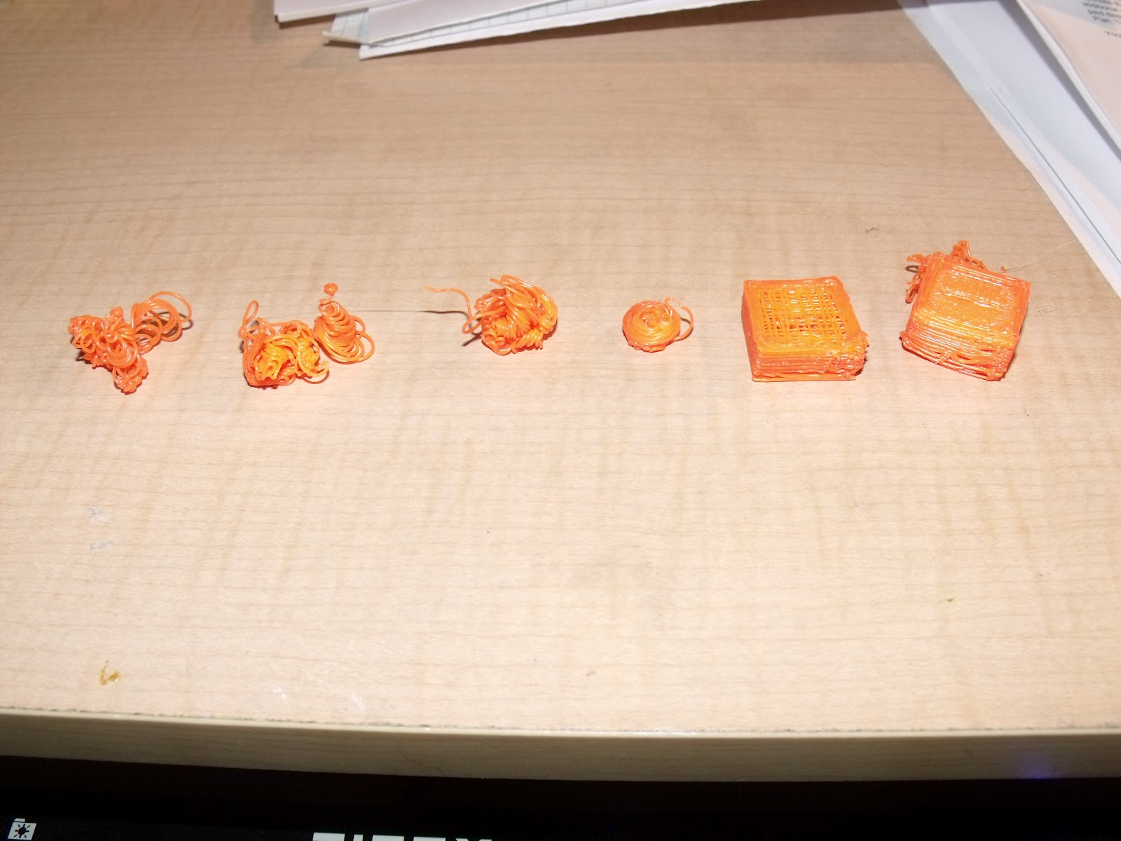
So I decided with the new upgrade I should try something a little more complex. I downloaded the STL files for a knot. Which is one continuous loop printed on a little platform. The loop never touches it self and passes through the various openings. This is something that would be impossible to machine so it definitely shows the capabilities of 3d printing. 

Time lapse of print. 1400mm of filament, 70min 15sec of print time


Finished, looks a little hairy in some sections but it will clean up nice

Just another view before cleanup


Post cleanup Top

Post Cleanup Side


Software Upgrade


So I decided to make the firmware switch from Sprinter to Marlin. Wow what a difference! Before on sprinter my circles were out of round by 1.1mm and were very jittery. With Marlin my circles are out of round by .3mm and runs smooth as butter. It also runs so much quieter. 

This is a Wades Extrusion gear comparison. The one on the right was Sprinter, the one on the left Marlin. Although it may be hard to tell from the picture, the Marlin print is much more round. The rest of the print quality on this part had major improvements. 


Some thoughts on Marlin.... The change over was very difficult for me. It took a few nights and hours of programming to get it to work correctly. It definitely improved quite a lot but was very frustrating. The direction are very unclear at best, and because every printer runs differently it was hard to get it configured. 

I also decided to get Autodesk 123d this past weekend! Pretty cool, I like it better than sketchup but still nowhere near Solidworks (which I wish I had)

Tweaking

So I spent a long time playing with different temperatures and layer thicknesses. I also seemed to be having too much fill causing the nozzle to drag on solid filled areas. I adjusted the ratio of filament output.

All of my test pieces, was keeping prints small to not waste filament and just test with settings. My optimal settings were 240 Degrees C, .95% extrude ratio (extrudes .95% of calibrated rate), Layer thickness .32mm. Ambient room temp for all prints so far has been around 70-75 degrees F

These tests are using Pronterface (GUI), Sprinter (Firmware), Slic3r (Gcode generator) and Google Sketchup.

New Print Bed

So previously I had mentioned that I upgraded to printing on a piece of glass from the Home Depot. Well, that was working very well but I was still getting some warping issues and sometimes the glass wouldn't seem that hot. It was suggested to make ABS juice out of dissolved ABS scraps, but I didn't really want to store acetone in my apartment.

An opportunity arose to get a hold of a sheet of flat ceramic. This is a little bigger than the heat bed, but the corners are rounded enough to make it fit. It is flat and parallel within .0002" but failed due to a large chip on one of the edges. Instead of letting it get shattered in the dumpster I asked permission to test this $1095 plate as a print surface. 

The ceramic heats more evenly than the glass ever did, and I do not have insulation under the heatbed like many suggest. The ceramic holds the heat very constant. The ABS would not stick to the bare ceramic so I still needed to use Kapton Tape. I purchased a 1" wide roll from Amazon. So far I have had no warping and the adhesion has been awesome. Even on some bigger prints (no pictures of those)

Wednesday, April 11, 2012

Extrude Axis Cooling Upgrade

This is a sweet upgrade I did. Haven't tested the cooling capability, but it looks like it will work well

Here is a cooling kit that I purchased for just 9.99! 2 heat-sinks, thermal paste, double sided thermal tape, and a heat-sink with build in fan. It also has to quick attach pushpins.

I immediately whipped up a bracket to fit around the extrude motor and line up with the mounting holes. The holes needed slight reaming. The print as a hole looks beautiful and only required about 300mm of filament 


End view of fan heat-sink to see how bracket was fitted. Underneath the copper I put down a full layer of kapton tape, this was to protect the motor from the thermal paste but still provide good conductivity. It also works as a vibration shield. 

Here is a side view showing the quick push pin. Hopefully I will be doing some heat testing tomorrow!
The smaller additional heat-sink might be placed on the face thats showing in the picture if needed. If not both extras will be put to use on the other motors. 


Update! 4/23
The extrude motor was still getting fairly hot so I added the small heat sink to the side with some of the double sided tape. Major improvement.


Monday, April 9, 2012

Temporary Cooling

Some of my current temporary cooling for my stepper motors. On the two 30-40 minute prints I have done the Extrude Motor gets very hot. Not to mention the X and Y motors get pretty warm. I can only imagine what they would be like for a few hour print. 

A thin ceramic plate attached to the extrude motor with a cooling fan blowing down on it did the trick! Only limits me to a small print area for now (ok no big parts yet)


Haha the fan wiring I'm proud of. I used an old scavenged server power supply fan with a very high airflow rate. I ran the wire back to a nine volt battery that is taped in place to one of the Z axis motors. I also hooked up a scavenged 115/230V switch out of a power supply (works just like an on off switch if you know how they work). Some alligator clips, electrical tape, and a paperclip make it complete. Oh yeah and the zip ties holding the fan so it blows onto that ceramic plate


X axis cooling. Now I particularly like this one. The are three ceramic L shaped pieces with a hole in them. The fit pretty snug to the motor and were easily zip tied in place. Will do the same to the Y axis.

Ceramic is an excellent conductor of heat. These small amounts of ceramic are very efficient at pulling heat off the motors. These ceramic parts are scrap parts from my workplace and I do have permission to use them. 

Saturday, April 7, 2012

Cylinder test and time lapse


Cylindricity Test. Wanted to see how round a cylinder would be since my cubes are now even. Slightly out of round but not too bad. 


Here is a time lapse video of a cube with 3 cylinder cut aways. The print took 20 minutes. 

Prints from yesterday. The cube, cylinder tests. Today I tried the box with cut outs. Didn't really turn out that well haha, I think it got to hot on the thin corners. 

12% Fill Test

Printing perimeter. For those new to this, the outer ring is to purge the nozzle out.

Printing the first layer.

Printing a cube with 12% fill.

Cube "finished." I did not allow it to print the top solid layers to see what the inside of a print looks like. Fill can be anywhere from nothing to solid. This is a way to save material and reduce print time


Thursday, April 5, 2012

Print Improvements


So prints in order, 4 on the right from yesterday. In order left to right
1. 20mm Box with shifted layers
2. 10mm Box didnt stick to build platform
3. 15mm cube 25% fill, didnt stick to platform
4. 15mm cube 25% fill, didnt stick to platform
5. Today: the same 20mm box. 15%fill. almost perfect
6. Today: 15mm cube. 15% fill. almost perfect
7. Today: tiered cylinders, kinda eggy
8. Today: a wades extruder gear bottom messed up

I turned up the trimpots to give my steppers some more power as recommended to me. It appears to have done the trick and removed my shifting layers. Just look how much nicer the prints are. I also slowed the speeds by 50% and upped the temp to 240 Degrees C (464*F). To get an idea, the 15mm cube took almost 5minutes and a little over 300mm of filament.

All of today's prints the bottom layer is messed up. Still not getting good adhesion to the build surface. Definitely huge improvements though! I just wish I could make that bottom layer stick.

Tuesday, April 3, 2012

Upgrades

Ok so here is my first full print... As you can see the layers shifted twice. Not sure why yet, that's tomorrows goal. Also I finished the print due to a new print surface! A sheet of picture frame glass on the heat bed made the ABS stick a lot better! Thanks for the help from the forums guys :)

I was sick of my heat bed automatically being on when I turn on the power supply (after just one night haha). So I took some old molex connectors out of an old power supply that is fried and made a quick plug. Maybe someday I will get it on a switch, but this will work for now. It also allows for a few other plug spots for some future cooling fans!

Monday, April 2, 2012

Printing!


So the ones on the left are extrusion rate calibrations, the right are 20mm cubes... they came delaminated from my print bed so I had to restart them. Hopefully tomorrow night i will have one full cube!

Video of my first print!

Investment Time/Money

Ok so now that I have all the materials its time to total everything up. Including the time for the build. I did not record time for the calibration and running tests, only the physical build.

Total Physical Build Time: 11hrs

BOM:

ItemSupplierItem ## Unit Cost  Total 
M8 Linear RodsMcMaster Carr90024A0806 $      8.31  $    49.86
M8 Threaded RodsMcMaster Carr1272T173 $    15.72  $    47.16
M8 Rods ShippingMcMaster Carr-- $     6.17  $      6.17
Nema 17 Stepper Motor, WiredUltimachine.comUMN17MTR5 $    21.50  $  107.50
Motor ShippingUltimachine.com-- $    10.66  $    10.66
"Vitamins", Heatbed, Plastic Parts
Extruder, Gen6 ElectronicsMakerfarm.comV2KIT1 $  439.95  $  439.95
Kit ShippingMakerfarm.com-- $    15.80  $    15.80
Power Supply 12VDC 20AEbay-1 $    28.78  $    28.78
Orange ABS Filament 2.64lbsEbay-1 $    32.00  $    32.00
Filament ShippingEbay-- $    30.00  $    30.00
Total Cost $  767.88

Update 4/3/12 had to add a sheet of glass. I bought picture frame replacement glass to put on the heat bed when printing (as recommended to me) since I had problems with my print sticking to the blue tape. This added $1.98

An important thing to note about the build cost is the actual build is 
767.88-62.00(consumables)+1.98(glass)=707.86

Power Supply


New power supply arrived! $28.78 +12VDC 20A power supply. I took a standard PC power cable and cut the end off to wire it up. If you do this BE SURE YOU KNOW WHAT YOU'RE DOING. This is very dangerous and caution needs to be taken. You need to make sure the proper wires are hooked up to the right locations and that the voltages are good. Make sure to use heavy enough wire (such as this power cord) for the AC input. 

I have been playing with the printer before this arrived, but with a "hotwired" computer power supply. Also please dont do this unless you are sure you know what you're doing as it is very dangerous.

Sunday, April 1, 2012

Victory!

So after hours of trouble shooting, trying four computers, I finally figured it out.... I needed to turn the power supply on. Stupid I know, but I honestly thought that the power supply just powered the motors and that the board got power through the USB port. Well I tried installing the drivers and everything again to get the computer to recognize it and it worked with the power on, and the whining of the motors stopped! Before this the whining was a very high-pitched noise that was really annoying. So maybe it had nothing to do with the trim pots! gonna turn them back up.